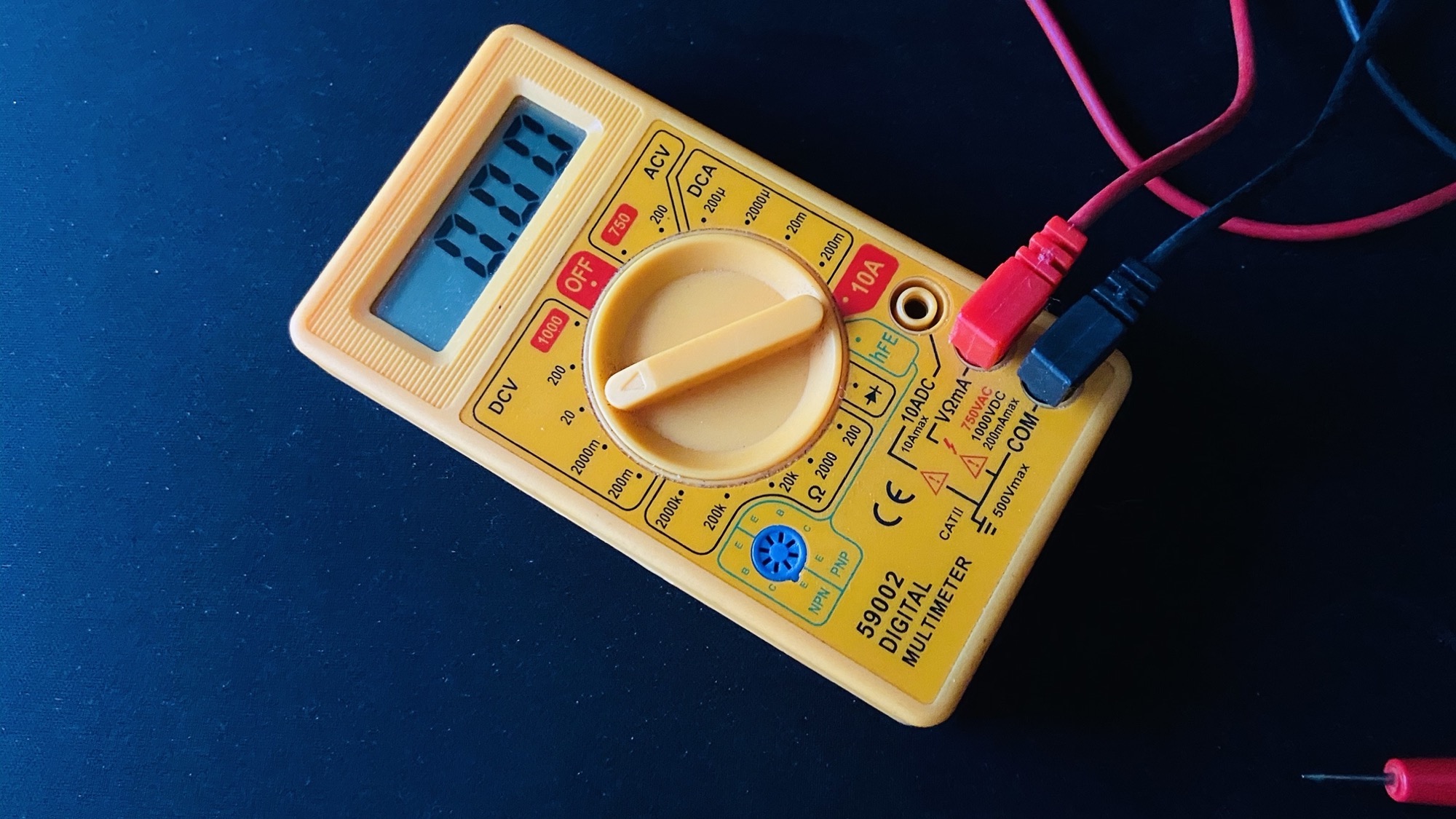
We all know the importance of testing electronic components. Even with advancements in electronic component testing, failures can happen. These failures might be due to inadequate testing during manufacture or insufficient manufacture testing. Electronic components need thorough testing and top-notch maintenance.
One of the most important tools in your toolbox — is a multimeter. Most appliances with electrical components go bad when some part of the circuit is no longer conducting electricity correctly, so being able to isolate the parts and test them will be a frequent part of your job.
A multimeter is an instrument designed to measure electric current, voltage, and usually resistance, typically over several ranges of value. A multimeter is an instrument that is mainly used to measure the three basic electrical characteristics of voltage, current, and resistance. It can also be used to test continuity between two points in an electrical circuit. They can also be used for testing batteries, household wiring, electric motors, and power supplies.
How to test some electronic components with a multimeter
Multimeters make it easy to automatically check the condition of various electrical components. First, determine what type of test you are performing, and select the appropriate setting. If you are checking for resistance, you will need to choose the Ohms setting, whereas you will need to choose either AC or DC if you are measuring voltage.
Electrical devices can malfunction or become damaged in a huge number of places, which is why it can sometimes be difficult to find the source of the problem. With tools like a multimeter, you can test the individual components of a device, helping you to pinpoint the issue, test components before use, perform routine testing and repairs, and more.
When using a multimeter, the most important step is to select a voltage or range that will be higher than the expected value of the component you plan to test. This will ensure an accurate reading and help to keep tools and equipment safe. Finally, when dealing with or trying to use an electronic component, it is important to disconnect from the power source.
How
to use a Multimeter to test common electric components
It is important that all Cables and wires should be tested before being used or added to a device, however, they can also be tested once they have already been installed. Cables are tested for continuity, assessing their ability to channel electrical charge and transport it from one place to another.
The first step in testing a capacitor or inductor is to ensure the unit is discharged. Set the multimeter to measure Ohms, and connect the probes to the terminals. If the meter reads "open line", the unit is in good condition. If there is no change, and no reading appears on the meter, the unit is dead.
- Battery
By using a multimeter to test a battery’s voltage, you can determine whether a battery is fully charged, in need of a charge, burnt out, about to burn out, and so on. By testing a battery for its voltage, you can rule out certain electrical issues, keep track of when batteries need replacing, and ensure your devices are being powered properly.
- Diodes
First, you need to disconnect the diode from its power supply and ensure that it is discharged. Then set the multimeter to ‘diode test’, and connect the meter probes to the diode leads. Test, and note the reading. Next, reverse the test probes and test again, also noting this reading. If the first reading shows 0.5V – 0.8V (silicon) or 0.2V – 0.3V (germanium), the diode is in good condition. If the reversed test reads OL (open line), the diode is confirmed to be in good condition. If the reading shows OL in both directions, the diode is dead. If the meter shows a reading of around 0.4V in both directions, the diode is short and needs to be replaced.
- Fuse
Connect the probes of the multimeter with the fuse, and set the meter to "resistance" mode. If the reading shows 0, the fuse is in good condition. If the reading shows "infinite", it is an indication of a problem and the fuse may need to be replaced.
- LEDs
First, disconnect the LED from its power source. Set the multimeter to "diode test", and connect the probes to the LED terminal. If the LED glows, it is in good condition- any other results shows a defect or lack of charge.
- Relays
Set the multimeter to "continuity", then attach the probes of the meter to the coil terminals of the relay. If the multimeter makes a sound or shows any reading of continuity, the coil is in good condition. If the meter shows no change or gives no indication of continuity, the relay is damaged and needs replacing.
Place the switch or push button in the ON position. Set the multimeter to "resistance", then attach the probes of the meter to both terminals of the switch or push button. This test should produce a reading of "0". Next, push the button or flip the switch to put it into the OFF position, then perform the test again. This test should produce a reading of "infinite". If both tests produce a reading of 0, or both tests produce a reading of infinite, the switch or button has malfunctioned and needs to be replaced.
Using a multimeter, you can test the base, collector snd emitter of a transistor.
Electronic components are set to get more complex, be it a
simple home appliance or advanced space technology. It is important to keep up
to speed with the upgrades in testing technology, and the right way to use it
to ensure safety.
You can learn more about multimeters and also share for
others to see.
 Share
Share